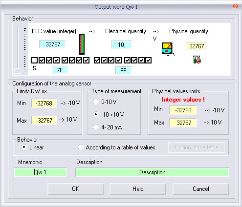
As the configuration or editing window shows, these output objects always behave in the following manner :
From the automaton data value to the electrical value then to the physical quantity.
The user must set the values :
the physical limits of the measurement range or of the set point value (i.e. from 0% to100% for the instruction to open a valve) ;
the standard type of acquisition card (0 to 10 V, -10 to +10 V, from 4mA to 20mA) ;
the limits of the acquisition card of the automaton (limits of the word treated by the automaton) ;
the fields of mnemonic and of description are not absolutely required.
Output word Qw x
The value indicated within the black frame always corresponds to the physical quantity.
Warning: the data value used in programming always corresponds to the automaton data value.
An info-bubble shown in the RUN mode gives the following information separated by a comma :
physical quantity ;
electrical value ;
automaton data value.
Editing an initial value :
in the Run mode, only the programming allows the modification of the PLC data word to be reflected on the physical quantity ;
in the creation mode, a left click opens the contextual menu allowing to edit this object. The introduction of an initial value is possible via the potentiometer ,or via an available dialog box which can be open by clicking on the label corresponding to the physical value ;
do not forget to validate the introduction by clicking on the OK button shown in the editing window.
Internal Word Mw
For
an internal word (MW) only the data of the PLC is to be taken into account.![]()
Parameterize the same limits for the physical quantities and for PLC data word and choose a linear behaviour !
Nonlinear behaviour (QW)
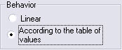
The behaviour of the acquisition card is linear by default.
The selection
of the option ‘’According to values table’’ allows to edit the table via
the button ![]()
According to the type of actuator (valve...), the behaviour of the acquisition is not always linear, it is recommended that you define behaviour tables of the physical quantity as a function of the electrical value.
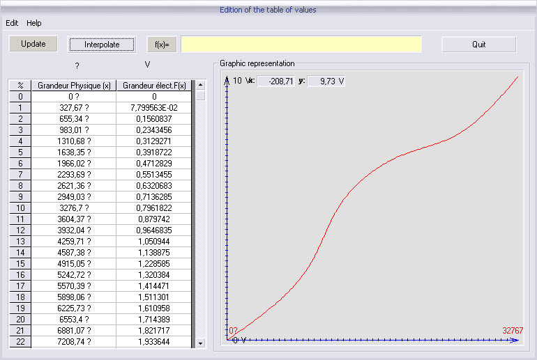
After editing, a validation is requested


![]()

![]()