Accessible from the menu "Virtual
Mechanism - Fluids - Valves" or from the toolbar ![]() .
.
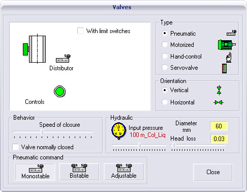
Modelling the valve is designed according to three criteria :
mechanical behaviour (opening speed) ;
type of drive ;
and hydraulic.
Parameter setting :
Choose the type of drive, the end stops used, the position orientation of the valve.
Choose the opening and closing speed.
The hydraulic behaviour: input pressure, head loss and diameter.
Assumptions :
For the first feeder valve, set the input pressure which will be always expressed in meters of height of column of liquid (m Cl).
This physical unit and the individual head loss allow the adaptation to all known fluids, fluid flow calculations are carried out in a turbulent flow mode.
Internal behaviour of valves :
The flow rate of a valve is calculated from the following formula
![]()
With :
Q is the flow rate ;
S la section de passage ;
Delta P is the pressure difference, head loss included.
The Delta P depends on the input pressure given either by the parameter setting or by the layout of piping the tank located upstream.
Nonlinear behaviour :
For servo-valves, it is possible to define a nonlinear behaviour of the flow rate according to the percentage of valve opening.
See parameter setting of an analog output word.
Info-bubble:
After placement of a valve, in Run mode, an info-bubble on the valve gives in real time :
the percentage of valve opening ;
the input pressure (m cl) ;
its output flow rate (m³/s).
From the toolbox you can place on the valve various sensors indicating :
the percentage of valve opening ;
the input pressure of the valve ;
the flow rate ( dm³/s ).
Those analog sensors must be calibrated according to your installation.
See parameter setting of an input analog.


![]()