Layout of pipings and behavior of the drawn hydraulic system.
After placing
the hydraulic elements such as tanks or valves, it is possible to connect them using
the piping layout mode from the toolbar ![]()
Warning, it is necessary to place a tank on the work area, otherwise it is not possible in layout mode to make the piping connections.
The layout of a pipe is done with the mouse by indicating the origin of the pipe and then the destination of the pipe.
It is possible to connect: valves with each other, a valve to a tank and vice-versa.
Deleting a component is done in the ‘Layout’ mode from the contextual menu (right click on the piping).
A few circuits
Example 1
1
The upstream valve is fed at a set input pressure and the flow results from the characteristics of the circuit downstream and the degree of opening of the valve.
When a valve fills a tank, the end of the filling pipe is assumed to be at atmospheric pressure. The pressure in
the valve must be sufficient to overcome the height of the liquid column.
When a tank feeds a valve, the input pressure of the valve corresponds to the difference in height of the liquid level and the geometrical height of the valve.
Example 2
Sharing the flow output of a tank between valves
At the direct output of a tank, ProcesSim allows to use only one valve!
If one wants to distribute the flow between several valves it is necessary to use a circuit such as that shown in the opposite figure (with the upstream valve normally opened).
Calculation assumptions :
The different flow outputs of the valves located downstream are calculated according to their diameter, the head loss, and their degree of opening. The valves constituting the circuit are considered to be at the same geometrical level and the exit of the valves is at atmospheric pressure.
This assumption is often verified in practice because of the larger magnitude of the input pressure compared to the small level differences.
Example 3 : Connection between tanks
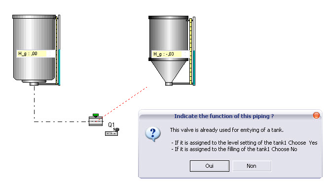
By answering Yes
one gets :
After switching in Run mode, when the communication valve is open, the levels equilibrate each other dynamically according to the laws of physics.
In the case where the tanks are located one above the other and by answering No one gets:
:
Beware : this is a forbidden set up, its operation is not correct
Example 4
Several tanks are connected to a valve.
After switching in Run mode, the levels balance each other dynamically according to the laws of physics.
Beware :
Since various flow outputs of the valves located downstream are calculated according to their diameter and their degree of opening, and the valves of the incoming circuit are assumed to be at the same geometrical height, and since the exit of the valves are assumed to be at atmospheric pressure, certain assemblies set up may be incorrect.
Correct Incorrect !