File Edit Mechanic virtuel Display Programming Parameters ?
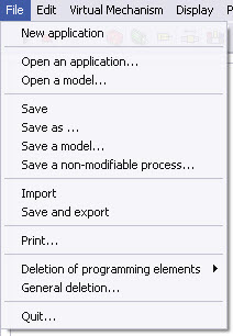
New application :
Create a new application.
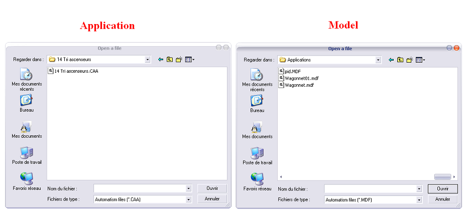
Open an application :
Open a CAA file application CAA or an MDF model file.
An application and a model can be saved under the same file name, only the file extensions and the saving options are different.
Save / Save as :
Allows to save your application at any time.
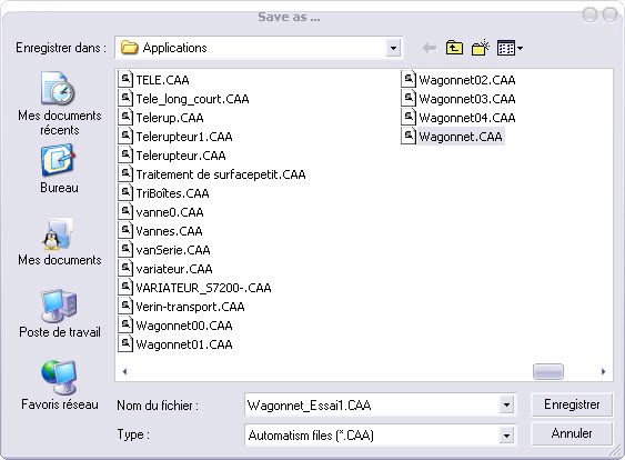
By default, the proposed location is the sub-folder "Applications"' of folder "ProcesSim" in "Programs Files" directory of your hard disk.
Notes :
If the file calls objects created or imported in the ProcesSim file named "Processim Drawings" you must also import the files containing those objects together with the files of their application. Various options for saving the new application are also proposed via the general index of the “Configuration option” window that can be displayed from the toolbar under Parameters–Preferences
The extension of the ProcesSim project files is ".CAA"
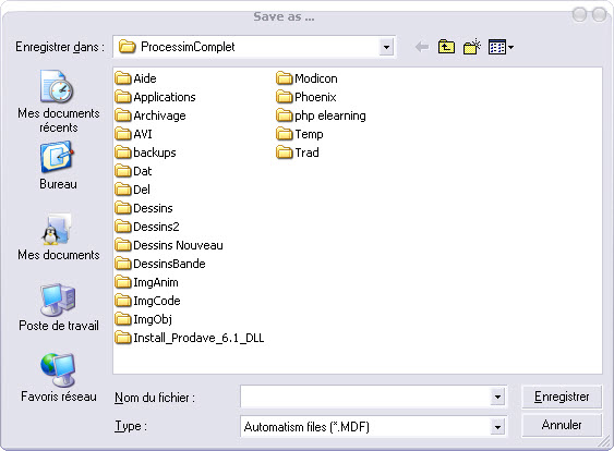
Saving a model file is restricted to trainers (via an access code). This allows them to prepare standard applications :
• operative part only ;
• operative part and components ;
• solved examples ;
• erroneous examples to correct ;
• …
The extension of these model files is : .MDF

Note :
The access code can be modified via the access thumb-index of the window “Configuration options” which you can select from the toolbar under Parameters - Preferences.
As for an ordinary application, the " .MDF " file is placed by default in the directory file : ProcesSim Applications.
Save a non-modifiable process :
Create a template (i.e. a document for the exclusive use of trainers via an access code), the user of this virtual process will not be allowed to modify or save the operative part.
Only programming is available.
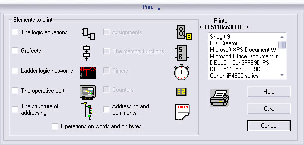
Print :
Printing of one part or of the entire project.
Deletion of the programming elements :
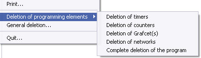
Deletion of Grafcets (SFC): deletion of all the SFC ;
Deletion of networks: deletion of the Ladder logic programming and deletion of the words operations ;
Deletion of the program: full program deletion (Ladder logic, Grafcet (SFC), timer, counter …..).
Remark :
The operative part is unchanged and the addressing remain the same if they have been programmed (see …’’Execution of a program in connected mode under option ‘’addressing’’).
Timers and counters existing on the work area and shown on the screen are deleted via the operative part.
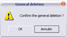
How to delete a project completely :
Complete deletion (program and operative part)
Quit :
You leave the session.
File Edit Mechanic virtual Display Programming Parameters ?
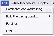
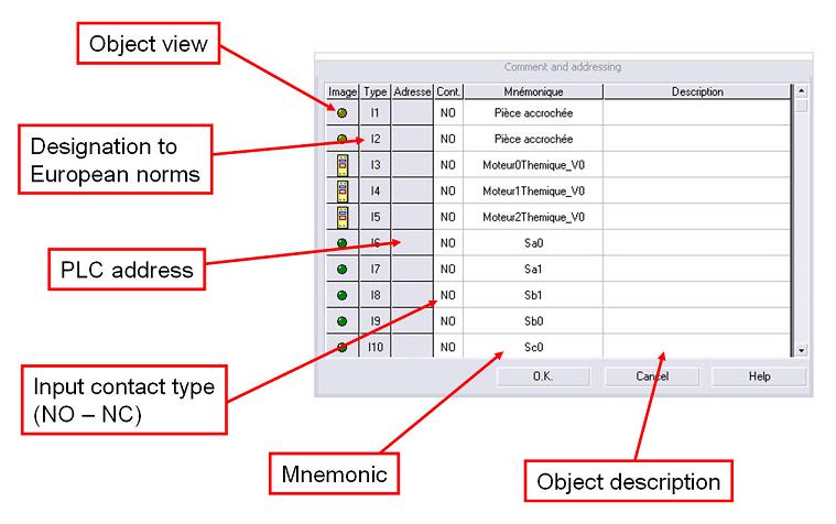
Comments and addressing :
This menu opens a window which allows you to edit the mnemonics, to give a description and to visualize the address screen, the address of the automaton used and the type of contact of each element used on the work area.
How to build the background image :
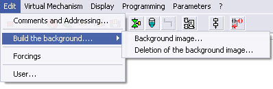
Allows the addition or the removal of a back image shown on the work area
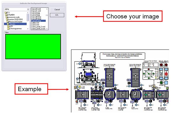
When the back image is added to the work area, all you need to do to set it in place is to double-click on it.
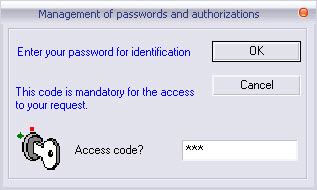
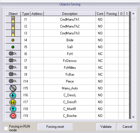
With your password (your Master password followed by 123), you can force changes in the signals received from or sent to the automaton in order to facilitate maintenance learning by provoking breakdowns in the installations.
User :
You can personalize your own title box.
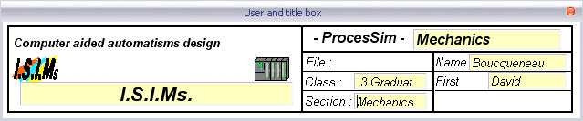
Note :
The title box appears only on the operative part diagram.
File Edit Virtual Mechanic Display Programming Parameters ?
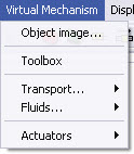
Object Images :
This menu allows you to set in place personalized interactive objects, i.e an image with the format *wmf, bmp, JPEG, GIF, ico* will be used as an interactive object. This object can be moved by: jacks, conveyors, conveying belts, tables of transfert, ...
Toolbox :
Contains the various tools for the assembly of your virtual operative part.
Tools for transfer objects :
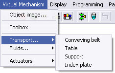
Addition of a conveyor for transporting object images.
A driving motor is also needed for allowing access to this window
Tools used to move images objects in connection with a linear positioner.
Allows to make a 30°, 45°, 60°, or 90° rotation of the objects present..
Fluids :
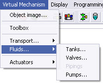
Tanks :
Addition of various types of tanks (cylindrical, conical, spherical).
Valves :
Addition of various valves (pneumatic , motorized valve, manual, servo-valve)
Piping :
Allows you to create own virtual piping.
Actuators :
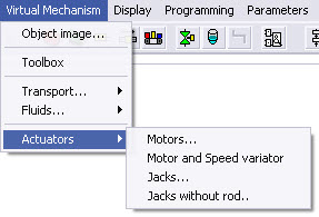
Motors :
Addition of asynchronous motors with their diagrams of integrated power (direct starting, 2 senses of rotation, star-delta starting ...).
Motors and speed variators :
Adding motors controlled by speed variators with integrated parameters (commands of speed, of acceleration and status word)
Jacks :
Addition of fully configured jacks.
Jacks without rod (positioner) :
Addition of a linear positioner.
File Edit Mechanic Virtual Display Programming Parameters ?
Symbolic PLC Address
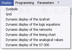
Grid :
Display a grid of points on the work screen for facilitating the alignment of operative parts.
Warning : the dynamic display will be activated in Run mode.
Dynamic display of SFC (Grafcet) :
Displays the SFCs with the receptivities and active steps.
Dynamic display of the logic equations :
Displays and animates the logic equations drawn on screen.
Displays the networks that you have programmed in " Ladder logic".
Dynamic display of timing charts :
Shows the evolution of the all or nothing signals.
Dynamic display of the analog values :
Displays the various analog data.
Dynamic display of the S7 300 :
Displays the front side of the Siemens S7-300 automaton and the control of transmitted and received data.
Available only on "ProcesSim - PLC Siemens" version.
File Edit Mechanic virtual Display Programming Parameters ?
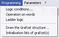
Access to the editor of logical building blocks (used in programming).
Access to the editor of operations and blocks "Move".
Access to the editor of the networks "Ladder logic".
To trace the structure of Grafcet :
Drawing of the sequences programmed with the SFC (GRAFCET).
Initialization bit of SFCs( grafcet) :
When these last bits go from ‘0’ to “1”, all the steps idendified as initial step are activated and all the other steps are deactivated.
File Edit Mechanic virtual Display Programming Parameters ?
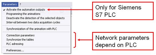
Activating the automaton outputs :
In mode drive,from the PLC, one can activate or deactivate the various addressed outputs of the automaton (Be careful with the wired equipment !).
Deactivate the detection of the selected objects :
Deactivate the detection function of photoelectric sensors for objects "manually " moved with the mouse.
Interval between two cycles of acquisition :
Sets the interval between two acquisition cycles of data and animations.
Synchronization of the animation with PLC :
Sychronization of the animation with PLC in real time with the PLC.
*Depends on the communication protocol
Communication protocol depends on the PLC type (ProcesSim version) :
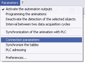
Set PLC type, the protocol and communication parameters.
Synchronize the addressings, the mnemonics and the descriptions with Step7.
Address input and output elements to PLC.
2. Schneider Electric TSX Micro/Premium version
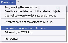
Hardware configuration of Tsx Micro :
Allow to configure the TSX PLC (type, bits number)
Allow to assign the differents inputs and outputs of the operative part on the PLC.
3. Schneider Electric Modicon M340 version
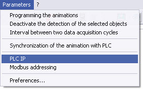
PLC IP :
Allow to define the station IP address and the first word necessary to the Modbus communication (by default : address %MW0)
Code to copy in the sub-routine into your Unity program.
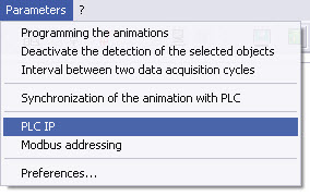
PLC IP :
Allow to define the station IP address and the first word necessary to the Modbus communication (by default : address %MW0)
Code to copy in the sub-routine into your PC WORX program.
The parameter setting of the various options of ProcesSim (automatic saving of languages, access code, screen resolution...).
File Edit Mechanic virtual Display Programming Parameters ?
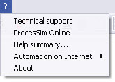
Technical support :
Address of the personnel providing technical support for the software.
ProcesSim Online :
ProcesSim website.
Help summary :
Educational software for handling project software.
The automation on Internet :
Links on line with our partners.
About :
Software Version - Development Team.